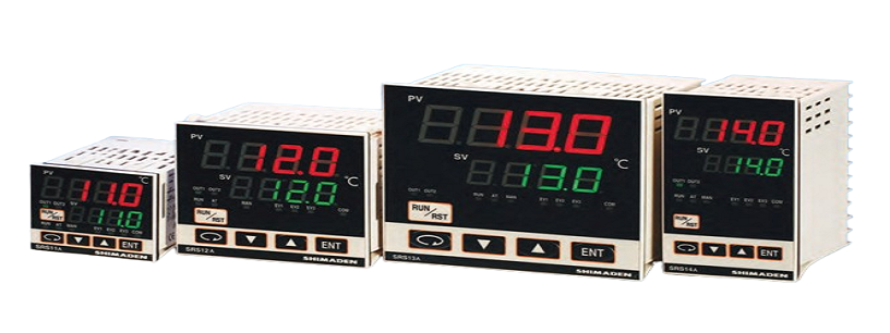
PID Controller SRS10A Series (SRS11A / SRS12A / SRS13A / SRS14A)
A controller with a space-saving depth of 62 x 65 mm compared to existing products with a depth of 100 mm. 3-point SV setting; 3 types of PID value can be set. Control output of ON/OFF hysteresis mode is selectable. Heating/cooling 2-output control (optional) can be selected. 4-pattern, 8-step program (optional) can be selected. 3-point maximum event output (optional) can be selected. Analog output (optional) can be selected. 2-point CT input (optional) can be selected. 4-point external control input maximum (optional), can be selected. Communication function (optional), master and slave mode can be used.
Share:
Feature:
- Multi-input and multi-range performance
- Small instrument depths (62mm – 65mm) save space, thus securing a larger installation area.
- SV setting: 3 points
- PID Value: 3 types
- 2-output heating and cooling control available (optional)
- Total 32 steps Program available (optional) (1-4 pattern, 32-8 step)
- RS-485 Interface available (optional) (Master/slave function, Modbus/Shimaden Protocol)
- Heater break/heater loop alarm (optional)
- A wide selection of additional functions (optional) is available to suit various needs.
- Possible to switch off SV/PV value by key operation
- Parameter mask (non-display) / lock (key lock) function
Ordering Information
SRS11A
| ITEM | CODE | SPECIFICATIONS | |||||||||||||||||
| SERIES | SRS11A- | DIN 48×48 Digital Controller | |||||||||||||||||
| INPUT | 8 | Multi-input | Thermocouple: B, R, S, K, E, J, T, N, PLII, WRe5-26, {U, L (DIN43710)}, AuFe-Cr |
||||||||||||||||
| R.T.D.: Pt100/JPt100 | Scaling Possible (inverse scaling impossible) Range: -1999 – 9999 Span: 10 – 10000 |
||||||||||||||||||
| Voltage (mV): -10 – 10, 0 – 10, 0 – 20, | |||||||||||||||||||
| 0 – 50, 0 – 100, 10 – 50 mV DC | |||||||||||||||||||
| 6 | Voltage (V) | -1 – 1, 0 – 1, 0 – 2, 0 – 5, 1 – 5, 0 – 10 V DC Input resistance: Min. 500 Kω |
|||||||||||||||||
| CONTROL OUTPUT 1 | Y | Contact: 1a, Contact capacity: 240 V AC 2A/resistive load Proportional cycle: 1 – 120 sec. |
|||||||||||||||||
| I | Current: 4 – 20 mA DC Load resistance: 600 Ω max |
||||||||||||||||||
| P | SSR drive voltage: 12 V±1.5 V DC/30mA max. Proportional cycle: 1 – 120 sec. |
||||||||||||||||||
| V | Voltage: 0 – 10 V DC Load current: 2 mA max. |
||||||||||||||||||
| CONTROL OUTPUT 1 | N- | None | |||||||||||||||||
| Y- | Contact: 1a, Contact capacity: 240 V AC 2A/resistive load Proportional cycle: 1 – 120 sec. |
||||||||||||||||||
| I- | Current: 4 – 20 mA DC Load resistance: 600 Ω max. |
||||||||||||||||||
| P- | SSR drive voltage: 12 V±1.5 V DC/30mA max. Proportional cycle: 0.5 – 120 sec. |
||||||||||||||||||
| V- | Voltage: 0 – 10 V DC Load current: 2 mA max. |
||||||||||||||||||
| Additional event output | E- | Additional event output 1 point (EV3) | |||||||||||||||||
| Additional external control input signal (DI) |
D- | Additional external control input 1 point (DI4) | |||||||||||||||||
| POWER SUPPLY | 90- | 100 – 240 V AC±10%, 50/60Hz | |||||||||||||||||
| 08- | 24 V AC/DC±10%, 50/60Hz | ||||||||||||||||||
| PROGRAM FUNCTION (OPTION) | N | None | |||||||||||||||||
| P | Max. 4 patterns Total number of steps: 32 | ||||||||||||||||||
| EVENT OUTPUT (OPTION) | 0 | None | |||||||||||||||||
| 1 | Event output 2 points (EV1, EV2) | ||||||||||||||||||
| ANALOG OUTPUT/ CONMMUNICATION FUNCTION (OPTION) |
0 | None | |||||||||||||||||
| 3 | 0 – 10 mVDC Output resistance: 10 Ω | ||||||||||||||||||
| 4 | 4 – 20 mADC Resistive load: 300 Ω max. | ||||||||||||||||||
| 6 | 0 – 10 VDC Load current: 2 mA max. | ||||||||||||||||||
| 5 | RS-485 (Shimaden standard protocol, MODBUS protocol) | ||||||||||||||||||
| EXTERNAL INPUT CONTROL SIGNAL (DI)/ CT INPUT (OPTION)/Note: CT sold separately |
0 | None | |||||||||||||||||
| 1 | CT input 2 points | ||||||||||||||||||
| 2 | Control input 3 points (DI1, DI2, DI3) | ||||||||||||||||||
| REMARKS | 0 | Without | |||||||||||||||||
| 9 | With | ||||||||||||||||||
| OPTIONAL ACCESSORIES | ||||||||||||||||
| Name | Code | Remarks | ||||||||||||||
| CT | QCC01 | CT for 30A (CTL-6-S) | ||||||||||||||
| CT | QCC02 | CT for 50A (CTL-12-S36-8) | ||||||||||||||
| Shunt resistor | QCS002 | 250Ω ±0.1% External receiving impedance for current input | ||||||||||||||
| Terminal Cover | QCR001 | For SRS11A | ||||||||||||||
SRS12A/SRS13A/SRS14A
| ITEM | CODE | SPECIFICATIONS | |||||||||||||||||
| SERIES | SRS12A- | DIN 72×72 Digital Controller | |||||||||||||||||
| SRS13A- | DIN 96×96 Digital Controller | ||||||||||||||||||
| SRS14A- | DIN 96×48 Digital Controller | ||||||||||||||||||
| INPUT | 8 | Multi-input | Thermocouple: B, R, S, K, E, J, T, N, PLII, WRe5-26, {U, L (DIN43710)}, AuFe-Cr |
||||||||||||||||
| R.T.D.: Pt100/JPt100 | Scaling Possible (inverse scaling impossible) Range: -1999 – 9999 Span: 10 – 10000 |
||||||||||||||||||
| Voltage (mV): -10 – 10, 0 – 10, 0 – 20, 0 – 50, 0 – 100, 10 – 50 mV DC |
|||||||||||||||||||
| 6 | Voltage (V) | -1 – 1, 0 – 1, 0 – 2, 0 – 5, 1 – 5, 0 – 10 V DC Input resistance: Min. 500 KΩ |
|||||||||||||||||
| CONTROL OUTPUT 1 | Y | Contact: 1a, Contact capacity: 240 V AC 2A/resistive load Proportional cycle: 1 – 120 sec. |
|||||||||||||||||
| I | Current: 4 – 20mA DC Load resistance: 600Ω max. |
||||||||||||||||||
| P | SSR drive voltage: 12V±1.5V DC/30mA max. Proportional cycle: 1 – 120 sec. |
||||||||||||||||||
| V | Voltage: 0 – 10 V DC Load current: 2 mA max. |
||||||||||||||||||
| CONTROL OUTPUT 2 (OPTION) |
N- | None | |||||||||||||||||
| Y- | Contact: 1a, Contact capacity: 240 V AC 2A/resistive load Proportional cycle: 1 – 120 sec. |
||||||||||||||||||
| I- | Current: 4 – 20 mA DC Load resistance: 600 Ω max. |
||||||||||||||||||
| P- | SSR drive voltage: 12 V±1.5 V DC/30 mA max. Proportional cycle: 1 – 120 sec. |
||||||||||||||||||
| V- | Voltage: 0 – 10 V DC Load current: 2 mA max. |
||||||||||||||||||
| Additional event output | E- | Additional event output 1 point (EV3) | |||||||||||||||||
| Additional external control input signal (DI) |
D- | Additional external control input 1 point (DI4) | |||||||||||||||||
| POWER SUPPLY | 90- | 100 – 240 V AC±10%, 50/60 Hz | |||||||||||||||||
| 08- | 24V AC/DC±10%, 50/60 Hz | ||||||||||||||||||
| PROGRAM FUNCTION (OPTION) | N | None | |||||||||||||||||
| P | Max. 4 patterns Total number of steps: 32 | ||||||||||||||||||
| EVENT OUTPUT (OPTION) | 0 | None | |||||||||||||||||
| 1 | Event output 2 points (EV1, EV2) | ||||||||||||||||||
| ANALOG OUTPUT (OPTION) | 0 | None | |||||||||||||||||
| 3 | 0 – 10 mVDC Output resistance: 10 Ω | ||||||||||||||||||
| 4 | 4 – 20 mADC Resistive load: 300 Ω max. | ||||||||||||||||||
| 6 | 0 – 10 VDC Load current: 2mA max. | ||||||||||||||||||
| CT INPUT (OPTION)/Note: CT sold separately | 0 | None | |||||||||||||||||
| 1 | CT input 2 points | Note: Available only when control output 1 or 2 is Y or P. | |||||||||||||||||
| EXTERNAL INPUT CONTROL SIGNAL (DI) (OPTION) | 0 | None | |||||||||||||||||
| 2 | Control input 3 points (DI1, DI2, DI3) | ||||||||||||||||||
| CONMMUNICATION FUNCTION (OPTION) | 0 | None | |||||||||||||||||
| 5 | RS-485 (Shimaden standard protocol, MODBUS protocol) | ||||||||||||||||||
| REMARKS | 0 | Without | |||||||||||||||||
| 9 | With | ||||||||||||||||||
| OPTIONAL ACCESSORIES | ||||||||||||||||
| Name | Code | Remarks | ||||||||||||||
| CT | QCC01 | CT for 30A (CTL-6-S) | ||||||||||||||
| CT | QCC02 | CT for 50A (CTL-12-S36-8) | ||||||||||||||
| Shunt resistor | QCS002 | 250Ω ±0.1% External receiving impedance for current input | ||||||||||||||
| Terminal cover | QCR002 | For SRS12A (3 pcs./set) | ||||||||||||||
| QCR007 | For SRS13A, SRS14A (2 pcs./set) | |||||||||||||||
Specification
| Display | ||
| Display methods | ||
| Digital display | Measured value (PV)/7 segments red LED 4 digits, target set value (SV)/7 segments green LED 4 digits | |
| SRS11A PV height of character: Approx. 12mm SV height of character: Approx. 9mm | ||
| SRS12A PV height of character: Approx. 15mm SV height of character: Approx. 12mm | ||
| SRS13A PV height of character: Approx. 20mm SV height of character: Approx. 13mm | ||
| SRS14A PV height of character: Approx. 12mm SV height of character: Approx. 9mm | ||
| Status display | LED lamp display | |
| Green: RUN, AT, MAN, OUT1, OUT2, COM | ||
| Orange: EV1, EV2, EV3 | ||
| Display accuracy | ±(0.25% FS+1 digit) Excluding cold junction temperature compensation accuracy of thermocouple input | |
| Accuracy if set value is lower than -100 ºC with K, T, U thermocouples is ±0.7%FS. | ||
| Accuracy guarantee not applicable to 400 ºC and below of B thermocouple. | ||
| Display accuracy maintaining range | 23 ºC± 5 ºc | |
| Display resolution | Depends on measuring range and scaling (0.001, 0.01, 0.1, 1) | |
| Measured value display range | -10 – 110% of measuring range | |
| (Range of Pt-200 – 600 ºC is -240 – 680 ºC, range of JPt-200 – 500 ºC is -240 – 570 ºC.) | ||
| Display updating cycle | 0.25 seconds | |
| Setting | ||
| Setting method | By operating 5 keys (PARA, DOWN, UP, ENT, RUN/RST) on the front panel | |
| Target value setting range | Same as measuring range (within setting limiter) | |
| Set value limiter | Individual setting for higher and lower limits, any value is selectable within measuring range. | |
| (Lower limit value<Higher limit value) | ||
| Key lock | OFF, 1 – 3 (4 level) | |
| OFF: No key lock | ||
| 1: Only user setting screen group and communication mode can be changed. | ||
| 2: Only SV and communication mode can be changed. | ||
| 3: Only key lock can be changed. | ||
| Parameter mask/lock function | Controls parameter displays/key locks | |
| Target parameter | STBY/EXE (RST/RUN) switching screen and all parameters except monitor screen (control for each screen group possible) | |
| PID screen group | Settings for each PID No. not possible (parameters are set by applying all PID Nos.) | |
| PROG screen group | Settings for each PTN No. not possible (parameters are set by applying all PROG Nos.) | |
| STEP screen group | Settings for each STEP No. not possible (parameters are set by applying all STEP Nos.) | |
| Input | ||
| Type of input | Selectable from multiple (TC, Pt, mV) and voltage (V) | |
| Thermocouple | B, R, S, K, E, J , T, N, PLII, WRe5-26, {U, L (DIN43710)}, Metal-chromel (AuFe-Cr) | |
| Input resistance | 500 kΩ minimum | |
| External resistance tolerance | 100 Ω maximum | |
| Burnout function | Standard feature (up scale) | |
| Cold junction compensation accuracy | ±2 ºC (between 5 and 45 ºC of ambient temperature), ±3 ºC if mounted closely | |
| R.T.D. | Pt100/JPt100, 3-wire type | |
| Amperage | 0.25 mA | |
| Lead wire tolerance resistance | 5 Ω maximum/wire (3 lead wires should have the same resistance.) | |
| Voltage mV | -10 – 10, 0 – 10, 0 – 20, 0 – 50, 10 – 50, 0 – 100 mV DC | |
| V | -1 – 1, 0 – 1, 0 – 2, 0 – 5, 1 – 5, 0 – 10 V DC | |
| Input resistance | 500 kΩ minimum | |
| Current input (0 – 20, 4 – 20 mA DC) is handled through external receiving impedance (250 Ω). | ||
| Input scaling function | Scaling possible for voltage (mV, V) input | |
| Scaling range | -1999 – 9999 units | |
| Span | 10 – 10000 units | |
| Position of decimal point | None, 1, 2 and 3 digits on the right of decimal point | |
| Sampling cycle | 0.25 seconds | |
| PV bias | -1999 – 2000 units | |
| PV filter | 0 – 9999 seconds | |
| PV gain | -5.00 – +5.00% | |
| Isolation | Not insulated from input, system, DI, and CT input but insulated from others | |
| Control | ||
| Control mode | ||
| With 1 output | Expert PID control with auto tuning function | |
| With 2 outputs | Expert PID control with auto tuning function PID (output 1) + PID (output 2) | |
| Type of control/rating (common to output 1 and 2) | Contact/1a 240 V AC 2A (resistive load) 1.2 A (inductive load) | |
| SSR drive voltage/12 V±1.5 V DC (maximum load current 30mA) | ||
| Current/4 – 20 mA DC (maximum load resistance 600Ω) | ||
| Voltage/0 – 10 V DC (maximum load current 2mA) | ||
| Control output resolution | Control output 1: approx. 0.008% (1/13000) | |
| Control output 2: approx. 0.008% (1/13000) | ||
| Output accuracy | Control output 1: ±1.0%FS (5 – 100% output) | |
| Control output 2: ±2.0%FS (5 – 100% output) | ||
| Control output 1 | ||
| Proportional band (P) | OFF, 0.1 – 999.9%FS (ON/OFF action by OFF) | |
| Integral time (I) | OFF, 1 – 6000 seconds (P or PD action by OFF) | |
| Derivative time (D) | OFF, 1 – 3600 seconds (P or PI action by OFF) | |
| Target value function | OFF, 0.01 – 1.00 | |
| ON/OFF hysteresis | 1 – 999 units (Effective when P=OFF) | |
| Manual reset | -50.0 – 50.0% (Effective when I=OFF) | |
| Output limiter | Lower limit 0.0 – 99.9%, higher limit 0.1 – 100.0% (Lower limit value < Higher limit value) | |
| Proportional cycle | 1 – 120 seconds (for contact and SSR drive voltage output) | |
| Control output 2 (option) | ||
| Proportional band (P) | OFF, 0.1 – 999.9%FS (ON/OFF action by OFF) | |
| Integral time (I) | OFF, 1 – 6000 seconds (P or PD action by OFF) | |
| Derivative time (D) | OFF, 1 – 3600 seconds (P or PI action by OFF) | |
| Target value function | OFF, 0.01 – 1.00 | |
| ON/OFF hysteresis | 1 – 999 units (Effective when P=OFF) | |
| Dead band | -1999 – 5000 units | |
| Output limiter | Lower limit 0.0 – 99.9%, higher limit 0.1 – 100.0% (Lower limit value < Higher limit value) | |
| Proportional cycle | 1 – 120 seconds (for contact and SSR drive voltage output) | |
| Manual control | ||
| Output setting range | 0.0 – 100.0% setting resolution: 0.1% | |
| Manual ↔ auto switching | Balanceless bumpless (within proportional range) | |
| Soft start | Set individually for output 1 and output 2 | |
| OFF, 1 – 120 seconds | ||
| AT point | SV value in execution | |
| Control output characteristic | RA (reverse action characteristic)/DA (direct action characteristic) switching by front key or communication | |
| Set individually for output 1 and output 2 | ||
| RA (reverse action characteristic): heating action | ||
| DA (direct action characteristic): cooling action | ||
| Isolation | Contact output isolated from all | |
| Analog output not insulated from SSR drive voltage, current and voltage output but insulated from others | ||
| (Control output 1 and 2 not insulated other than contact output) | ||
| Event output (option, 3 points maximum) | ||
| Number of output points | 3 points maximum (EV1, EV2, EV3) | |
| However, EV3 is exclusive selection from control output 2 and DI4. | ||
| Types | Selectable from the following 20 types for EV1, EV2 and EV3: | |
| no assignment, higher limit deviation alarm, lower limit deviation alarm, outside higher/lower limit deviation alarm, inside higher/lower limit deviation alarm, higher limit absolute value alarm, lower limit absolute value alarm, scaleover, EXE signal (RUN signal), output 1 inverted output (Contact output only), heater 1 break/loop alarm, heater 2 break/loop alarm, step signal, pattern signal, program end signal, hold signal, program signal, upslope signal, downslope signal, guarantee soak signal |
||
| Event setting range | ||
| Absolute values | Within measuring range (both higher limit and lower limit) | |
| Deviations | -1999 – 2000 units (both higher limit and lower limit) | |
| Higher/lower limit deviations | 0 – 2000 units (within/outside) | |
| Event action | ON/OFF action | |
| Hysteresis | 1 – 999 units | |
| Standby action | Selectable from following 4 types | |
| 1 Without standby action | ||
| 2 Standby 1 (when power is applied, STBY (RST)→EXE (RUN)) | ||
| 3 Standby 2 (when power is applied, STBY (RST)→EXE (RUN), execution SV is changed.) | ||
| 4 Control mode (without standby action: no alarm is output at the time of abnormal input.) | ||
| Output type/rating | Contact (EV1, EV2/ 1a x 2 points common EV3/ 1a independent)/ 240V AC 2A (resistive load) | |
| Output updating cycle | 0.25 seconds | |
| Latching function | Alarm action holding function (can be assigned for deviation alarm/absolute value alarm and heater break alarm) | |
| ON (effective)/OFF (not effective) selection | ||
| Unlatched by key operation, DI or communication when latching | ||
| Output characteristic | Selectable from NO and NC | |
| Isolation | Isolated from all | |
| Programming function (option) | ||
| No. of pattern | Maximum 4 patterns (can be set to 1, 2 and 4) | |
| No. of step | Maximum 8 steps (4 patterns), 16 (2 patterns), 32 (1 pattern) | |
| Total number of steps = 32 | ||
| No. of PID type | Maximum 3 | |
| Time setting | 0 minutes 0 seconds – 99 minutes 59 seconds/1 step or 0 hours 0 minutes – 99 hours 59 minutes/1 step | |
| Setting resolution | 1 minute or 1 second | |
| Time accuracy | ±(setting time x 0.005 + 0.25 seconds) | |
| Setting parameter for each step | SV, step time, PID No. | |
| No. of pattern execution | Maximum 9999 | |
| PV start | ON/OFF | |
| Hold | Possible either by front panel key input, external control input or communication | |
| Advance | Possible either by front panel key input, external control input or communication | |
| Power failure compensation | None (setting contents are maintained and elapsed time, execution step and number of execution are reset.) | |
| Guarantee soak zone | OFF, 1 – 999 units | |
| External control input (DI) (option) | ||
| Number of input points | ||
| SRS11A | Maximum 4 points: Exclusive selection with 3 points CT input (DI1, DI2, DI3) | |
| Exclusive selection with 1 point (DI4), control output 2 and event output (EV3) | ||
| SRS12A, 13A, 14A | Maximum 4 points: 3 points (DI1, DI2, DI3) no exclusive selection | |
| Exclusive selection with 1 point (DI4), control output 2 and event output (EV3) | ||
| Type of DI assignment | Selectable from the following 14 types for each DI. | |
| No assignment, EXE1 (RUN1) (control execution/suspension), EXE2 (RUN2) (control execution/ suspension), MAN (manual output), AT (auto tuning), ESV2 (SV external selection 2 bit), ACT1 (output 1 output characteristics), ACT2 (output 2 output characteristics), PROG (programming), HLD (hold), ADV (advance), PTN2 (start pattern selection 2 bit), PTN3, (start pattern selection 3 bit), L_RS (unlatching) | ||
| Action input | Non-voltage contact or open collector (level action) Approx. 5V DC 1mA maximum | |
| Input minimum holding time | 0.25 seconds | |
| Isolation | Not insulated from DI input, system, and CT input but insulated from others | |
| CT input (option) | 2 points selectable when the type of control output (OUT1, OUT2) is contact or SSR | |
| In case of SRS11A, exclusive selection with DI1, DI2 and DI3 | ||
| Types of current detection target | Assignable for OUT1 and OUT2 | |
| Current detection method | By CT sensor (sold separately) | |
| Current capacity | 30A/50A | |
| Current setting range | OFF, 0.1 – 50.0 A (alarm action off when set to OFF) | |
| Setting resolution | 0.1A | |
| Current display range | 0.0 – 55.0A | |
| Display accuracy | ±2.0 A (for sine wave 50 Hz) | |
| Alarm action | Heater break detection when control output ON: Alarm output ON | |
| Heater loop alarm detection when control output OFF: Alarm output ON | ||
| Alarm output | Assignable for event output (EV1, 2, 3) | |
| Minimum time for action confirmation | ±0.25 seconds for both ON and OFF (each 0.5 second) | |
| Alarm maintain mode | Selectable from latching function ON (effective)/OFF (non-effective) | |
| Standby action | Selection of “OFF” or “ON” (1, 2, 3) (Standby when power applied only) | |
| Sampling cycle | 0.25 seconds | |
| Isolation | Not insulated from CT input, input, system and DI but insulated from others | |
| Communication function (option) | Exclusive selection with analog output for SRS11A | |
| Type of communication | EIA standard RS-485 | |
| Communication system | 2-line half duplex start-stop synchronization system | |
| Communication speed | 1200, 2400, 4800, 9600, 19200, 38400 bps | |
| Data format | Selectable from 7E1, 7E2, 7N1, 7N2, 8E1, 8E2, 8N1, 8N2 | |
| Communication delay time | 1 – 100 (x 0.512 msec) | |
| Max. number of connections | 32 including host | |
| Communication address | 1 – 255 | |
| Communication code | ASCII, MODBUS RTU binary code only | |
| Communication protocol | Shimaden standard protocol / MODBUS ASCII, RTU | |
| Other | Start character and BCC operating method can be selected | |
| Communication memory mode | Selectable from EEP, RAM and r_E | |
| Communication master mode | Can be used as master device when using multiple units | |
| Start slave address setting | Broadcast, 1 – 255 | |
| End slave address setting | Start address – start address +30 | |
| Write-in data address settng | 0000H – FFFFH | |
| Communication distance | Max. 500 m (differs according to conditions) | |
| Isolation | Isolation for all | |
| Analog output (option) | Exclusive selection with communication for SRS11A | |
| Number of output points | 1 point | |
| Types of output | Selectable from measured value, target set value (execution SV), control output 1 and control output 2 | |
| Output signal/rating | Current 4 – 20 mA DC (max. load resistance 300Ω) | |
| Voltage 0 – 10 V DC (max. load current 2 mA) | ||
| Voltage 0 – 10 mV DC (output resistance 10Ω) | ||
| Output scaling | Within measuring range or output range (Inversed scaling possible) | |
| Output accuracy | ±0.3%FS (for display value) | |
| Output resolution | Approx. 0.008% (1/13000) | |
| Output updating cycle | 0.25 seconds | |
| Output limiter | Lower limit 0.0 – 99.9%, higher limit 0.1 – 100.0% (Lower limit value<Higher limit value) | |
| Isolation | No isolation with control output P, I and V | |
| General specifications | ||
| Data storage | Non-volatile memory (EEPROM) | |
| Ambient conditions for operations | ||
| Temperature | -10 – 50 ºC | |
| Humidity | Max. 90 %RH (no dew condensation) | |
| Elevation | Max. 2000 m above sea level | |
| Category | II | |
| Pollution class | 2 | |
| Storage temperature | -20 – 65 ºC | |
| Supply voltage | 100 – 240V AC±10%, 50/60Hz or 24 V AC/DC±10% | |
| Input/noise removal ratio | Normal mode 50dB minimum (50/60 Hz) | |
| Insulation resistance | Between input/output terminals and power terminal Min. 500V DC, 20 MΩ | |
| Dielectric strength | Between input/output terminals and power terminal, 2300 V AC, 1 minute | |
| Power consumption | ||
| SRS11A | Max. 11VA for 100 – 240 V AC | |
| 6VA for 24 V AC | ||
| 4W for 24 V DC | ||
| SRS12A, 13A, 14A | Max. 14VA for 100 – 240 V AC | |
| 8VA for 24 V AC | ||
| 6W for 24 V DC | ||
| Applicable standards | EMC | EN61326-1 |
| Safety | IEC61010-1 and EN61010-1 | |
| RoHS | EN50581 | |
| Material of case | PC resin molding (UL94V-0) | |
| External dimensions | SRS11A: H48 × W48 × D66 mm (in panel 62mm) | |
| SRS12A: H72 × W72 × D69 mm (in panel 65mm) | ||
| SRS13A: H96 × W96 × D69 mm (in panel 65mm) | ||
| SRS14A: H96 × W48 × D66 mm (in panel 62mm) | ||
| Panel thickness | 1.0 – 3.5 mm | |
| Panel cutout | SRS11A: H45 × W45 mm | |
| SRS12A: H68 × W68 mm | ||
| SRS13A: H92 × W92 mm | ||
| SRS14A: H92 × W45 mm | ||
| Weight | SRS11A: Approx. 120 g | |
| SRS12A: Approx. 190 g | ||
| SRS13A: Approx. 220 g | ||
| SRS14A: Approx. 160 g | ||
Releted Products
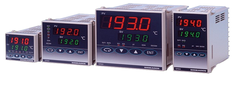
PID Controller SR90 Series ( SR91/ SR92 / SR93 / SR94)
Feature:
- Multi-input and multi-range performance
- Large 20mm bright display (SR93)
- Readable from a distance and in a low light area
- 2-output heating and cooling control available
- RS232C or RS485 Interface (MODBUS / Shimaden) available
- Dust and splash proof front panel equivalent to IP66
- A wide selection of additional functions (optional) is available to suit various needs.
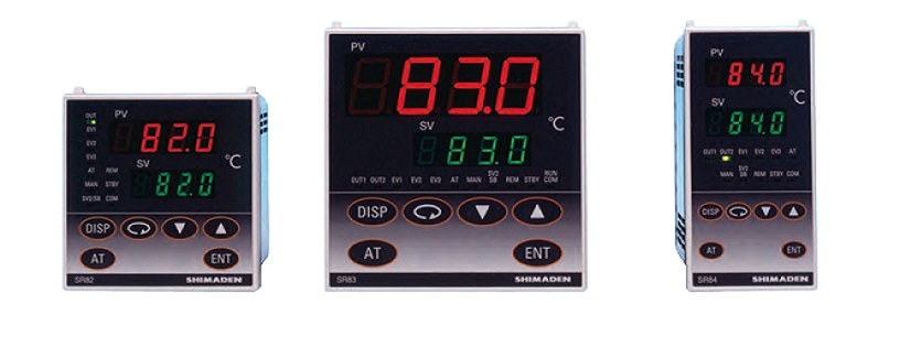
PID Controller SR80 Series ( SR82 / SR83 / SR84)
Shimaden SR80 series are suitable for applications with higher accuracy control is required.
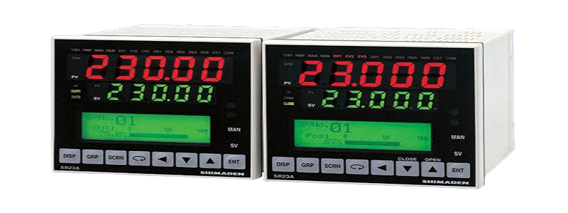
PID Controller SR23A
Feature:
- 2-channel controller (Basic type: 1-channel controller)
- Independent 2-loop / Internal Cascade / 2-input operation control
- High accuracy ± (0.1% FS + 1 digit)
- High Sampling Cycle 0.1 sec.
- High resolution 1/ 1000 °C display achieved
- *Only for R.T.D. input (scale: 0.000–30.000 °C)
- Auto-Tuning PID / Expert PID / Self-Tuning PID Multi-Setting of 10 Set Values
- Independent Multi -Input
- User Friendly Operation (Menu Driven: 4 Lines LCD Display)
- Easy Setting & Maintenance via Infrared COM port on the front panel
- Interface RS-232C/RS-485 (MODBUS / Shimaden)
- The front dust/splash-proof IP66
- Universal Power Supply (100–240V AC ±10%)
- Sensor power supply