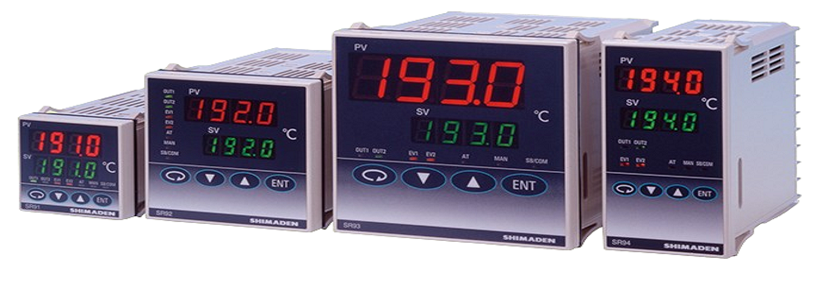
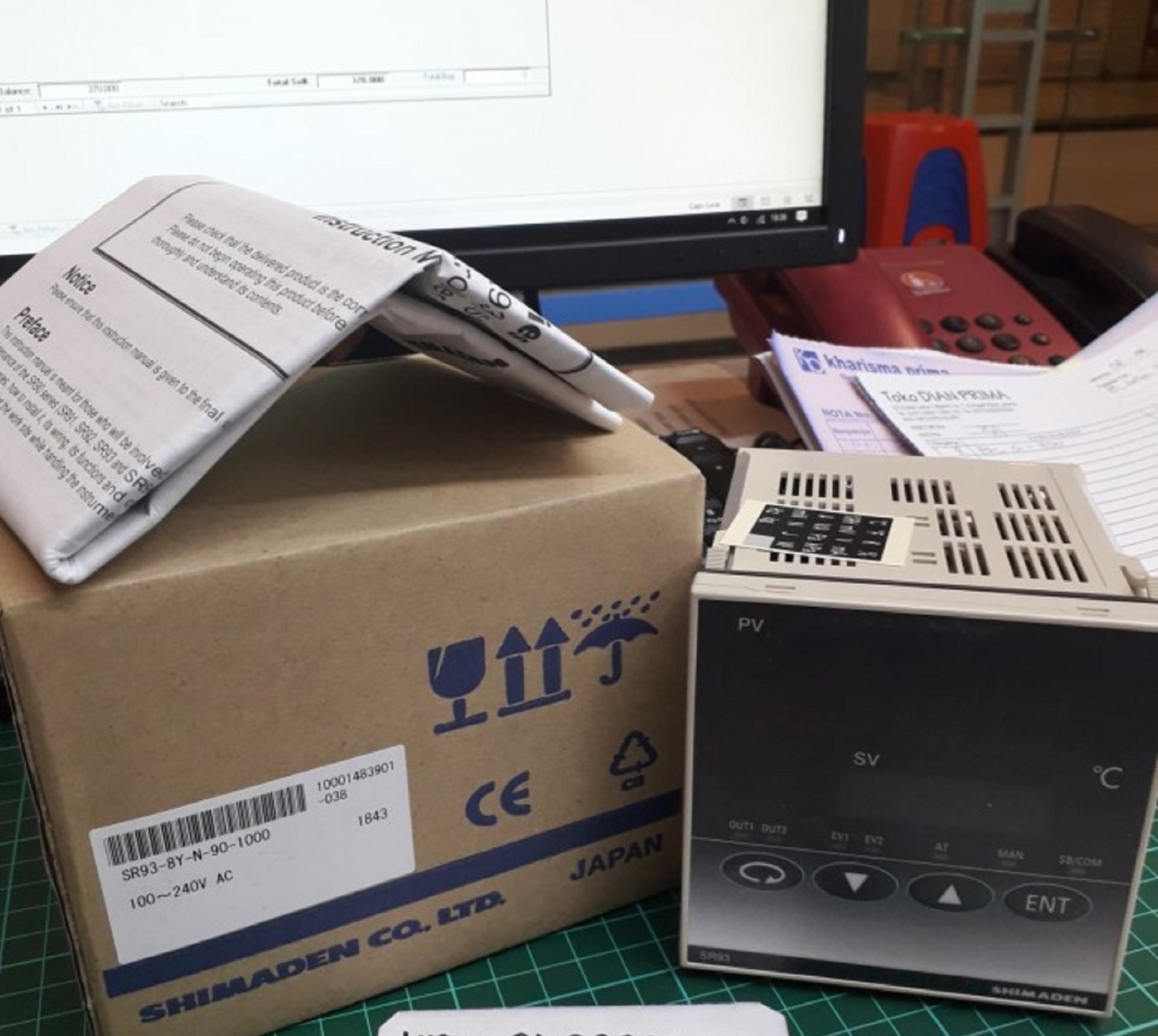
PID Controller SR90 Series ( SR91/ SR92 / SR93 / SR94)
Feature:
- Multi-input and multi-range performance
- Large 20mm bright display (SR93)
- Readable from a distance and in a low light area
- 2-output heating and cooling control available
- RS232C or RS485 Interface (MODBUS / Shimaden) available
- Dust and splash proof front panel equivalent to IP66
- A wide selection of additional functions (optional) is available to suit various needs.
Multi-purpose controller for multi-input (thermocouple, RTD, mV).
External Dimensions for SR90 Series:
-
SR91: H48 × W48 × D111 (Panel depth: 100) mm
-
SR92: H72 × W72 × D111 (Panel depth: 100) mm
-
SR93: H96 × W96 × D111 (Panel depth: 100) mm
-
SR94: H96 × W48 × D111 (Panel depth: 100) mm
Ordering Information
SR91
ITEM CODE SPECIFICATIONS SERIES SR91- MPU-Based Auto-Tuning PID Digital Controller, DIN H48 × W48 × D110mm INPUT 8 Multi input Thermocouple: B, R, S, K, E, J, T, N, PLII, Wre5-26 {U, L (DIN 43710)} R.T.D.: Pt100Ω /JPt100Ω Voltage: -10~10, 0~10, 0~20, 0~50, For voltage and current input:
Scaling Possible
Range: -1999~9999
Span: 10~5000
Note: Inverse scaling is not possible10~50, 0~100mV DC 4 Current (mA): 0~20, 4~20mA DC
Receiving impedance: 250Ω6 Voltage (V): -1~1, 0~1, 0~2, 0~5,
1~5, 0~10V DCCONTROL OUTPUT (1) Y- Contact: 1a, Contact capacity: 240V AC 2.5A/resistive load
Proportional cycle: 1~120 sec.I- Current: 4~20mA DC
Load resistance: 600Ω max.P- SSR drive voltage: 12V±1.5V DC/30mA max.
Proportional cycle: 1~120 sec.V- Voltage: 0~10V DC
Load current: 2mA max.POWER SUPPLY 90- 100~240V AC±10%, 50/60Hz 08- 24V AC/DC±10%, 50/60Hz EVENT OUTPUT (OPTION) 0 None 1 Contact output (2a) Ev1, Ev2: 240V AC 1A/resistive load N None OPTION Control output (2) Y Contact: 1a, Contact capacity: 240V AC 2.5A/resistive load
Proportional cycle: 1~120 sec.I Current: 4~20mA DC
Load resistance: 600Ω max.P SSR drive voltage: 12±1.5V DC/30mA max.
Proportional cycle: 1~120 sec.V Voltage: 0~10V DC
Load current: 2mA max.Heater break alarm 1 Current setting range: 0.1~30.0A
(with CT 30A)Note: Available only when control output (1) is Y or P and when event output is selected. 2 Current setting range: 0.1~50.0A
(with CT 50A)Analog output 3 Voltage: 0~10mV DC, Output resistance: 10Ω 4 Current: 4~20mA DC, Load resistance: 300Ω max. 6 Voltage: 0~10V DC, Load current: 2mA max. Communication 5 RS-485 (Shimaden standard protocol / MODBUS (RTU / ASCII)) SV Bias / DI 8 DI (set value bias, STBY, or ACT) 1 point, Non-voltage contact or Open collector input
Open collector input rating: approx. 5V/1mA max.REMARKS 0 Without 9 With (Please consult before ordering.) SR92
ITEM CODE SPECIFICATIONS SERIES SR92- MPU-Based Auto-Tuning PID Digital Controller, DIN H72 × W72 × D110mm INPUT 8 Multi input Thermocouple: B, R, S, K, E, J, T, N, PLII, Wre5-26 {U, L (DIN 43710)} R.T.D.: Pt100Ω /JPt100Ω Voltage (mV): -10~10, 0~10, 0~20, For voltage and current input:
Scaling Possible
Range: -1999~9999
Span: 10~5000
Note: Inverse scaling is not possible0~50, 10~50, 0~100mV DC 4 Current (mA): 0~20, 4~20mA DC
Receiving impedance: 250Ω6 Voltage (V): -1~1, 0~1, 0~2, 0~5, 1~5,
0~10V DC Input resistance: 500kΩ min.CONTROL OUTPUT (1) Y- Contact: 1a, Contact capacity: 240V AC 2A/resistive load
Proportional cycle: 1~120 sec.I- Current: 4~20mA DC
Load resistance: 600Ω max.P- SSR drive voltage: 12V±1.5V DC/30mA max.
Proportional cycle: 1~120 sec.V- Voltage: 0~10V DC
Load current: 2mA max.CONTROL OUTPUT (2)
(OPTION)N- None Y- Contact: 1a, Contact capacity: 240V AC 2A/resistive load
Proportional cycle: 1~120 sec.I- Current: 4~20mA DC
Load resistance: 600Ω max. (RA when shipped)P- SSR drive voltage: 12V±1.5V DC/30mA max.
Proportional cycle: 1~120 sec.V- Voltage: 0~10V DC
Load current: 2mA max.POWER SUPPLY 90- 100V~240V AC±10%, 50/60Hz 08- 24V AC/DC±10%, 50/60Hz EVENT OUTPUT/
HEATER BREAK ALARM (OPTION)0 None 1 Event output (2a) Ev1, Ev2
Contact capacity: 240V AC 1A/resistive load2 Event output (Ev1) + Heater break alarm
(with CT30ANote: Available only when control output (1) is Y or P is selected 3 Event output (Ev1) + Heater break alarm
(with CT50AANALOG OUTPUT (OPTION) 0 None 3 Voltage: 0~10mV DC, Output resistance: 10Ω 4 Current: 4~20mA DC, Load resistance: 300Ω max. 6 Voltage: 0~10V DC, Load current: 2mA max. COMMUNICATION OR SV Bias/DI (OPTION) 0 None 5 RS-485 (Shimaden standard protocol / MODBUS (RTU / ASCII)) 7 RS-232C (Shimaden standard protocol / MODBUS (RTU / ASCII)) 8 DI (set value bias, STBY, or ACT) 1 point, Non-voltage contact or Open collector input
Open collector input rating: approx. 5V/1mA max.REMARKS 0 Without 9 With (Please consult before ordering.) SR93/SR94
ITEM CODE SPECIFICATIONS SERIES SR93- MPU-Based Auto-Tuning PID Digital Controller, DIN H96 × W96 × D110mm SR94- MPU-Based Auto-Tuning PID Digital Controller, DIN H96 × W48 × D110mm INPUT 8 Multi input Thermocouple: B, R, S, K, E, J, T, N, PLII, Wre5-26 {U, L (DIN 43710)} R.T.D.: Pt100Ω /JPt100Ω Voltage: -10~10, 0~10, 0~20, For voltage and current input:
Scaling Possible
Range: -1999~9999
Span: 10~5000
Note: Inverse scaling is not possible0~50, 10~50, 0~100mV DC 4 Current (mA): 0~20, 4~20mA DC
Receiving impedance: 250Ω6 Voltage (V): -1~1, 0~1, 0~2, 0~5, 0~10V DC
Load resistance: 600Ω max.CONTROL OUTPUT (1) Y- Contact: 1a, Contact capacity: 240V AC 2A/resistive load
Proportional cycle: 1~120 sec.I- Current: 4~20mA DC
Load resistance: 600Ω max.P- SSR drive voltage: 12V±1.5V DC/30mA max.
Proportional cycle: 1~120 sec.V- Voltage: 0~10V DC
Load current: 2mA max.CONTROL OUTPUT (2)
(OPTION)N- None Y- Contact: 1a, Contact capacity: 240V AC 2A/resistive load
Proportional cycle: 1~120 sec.I- Current: 4~20mA DC
Load resistance: 600Ω max.P- SSR drive voltage: 12V±1.5V DC/30mA max.
Proportional cycle: 1~120 sec.V- Voltage: 0~10V DC
Load current: 2mA max.POWER SUPPLY 90- 100~240V AC±10%, 50/60Hz 08- 24V AC/DC±10%, 50/60Hz EVENT OUTPUT/
HEATER BREAK ALARM (OPTION)0 None 1 Event output (2a) Ev1, Ev2
Contact capacity: 240V AC 1A/resistive load2 Event output (Ev1) + Heater break alarm
(with CT30A)Note: Available only when control output (1) is Y or P is selected 3 Event output (Ev1) + Heater break alarm
(with CT50A)OPTION 00 None Analog output 30 Voltage: 0~10mV DC, Output resistance: 10Ω 40 Current: 4~20mA DC, Load resistance: 300Ω max. 60 Voltage: 0~10V DC, Load current: 2mA max. SV Bias / DI 08 DI (set value bias, STBY, or ACT) 1 point, Non-voltage contact or Open collector input
Open collector input rating: approx. 5V/1mA max.Analog output +
SV Bias / DI38 Voltage: 0~10mV DC, Output resistance: 10Ω
DI (set value bias, STBY, or ACT) 1 point48 Current: 4~20mA DC, Load resistance: 300Ω max.
DI (set value bias, STBY, or ACT) 1 point68 Voltage: 0~10V DC, Load current: 2mA max.
DI (set value bias, STBY, or ACT) 1 pointCommunication 05 RS-485 (Shimaden standard protocol / MODBUS (RTU / ASCII)) 07 RS-232C (Shimaden standard protocol / MODBUS (RTU / ASCII)) REMARKS 0 Without 9 With (Please consult before ordering.) Note:
When you purchase a two-output type controller and use it in a one output capacity, larger overshooting or undershooting may happen as a result of integral operation. Therefore, we recommend you to choose a one-output type. The cause of the above-mentioned problem is that the positional relationship between the proportional band (PB) and the set value (SV) of a one-output type controller differs from that of a two-output type.
Specification
| Display | |
| Digital display | Measured value (PV)/7 segments red LED 4 digits |
| Target set value (SV)/7 segments green | |
| Display accuracy | ±(0.3%FS + 1 digit) |
| Excluding reference contact temperature compensation accuracy of thermocouple input. | |
| Accuracy of readings lower than −100˚C of thermocouples K, T, U inputs is ±0.7%FS. | |
| Accuracy guarantee not applicable to 400˚C (752˚F) and below of B thermocouple. | |
| Display accuracy maintaining range | 23˚C ± 5˚C (18~28˚C) |
| Display resolution | Depends on measuring range (0.001, 0.01, 0.1 and 1) |
| Measured value display range | −10%~110% of measuring range |
| Display updating cycle | 0.25 seconds |
| Action display/color | 7 type, LED lamp display |
| Control output (OUT1, OUT2)/Green | |
| Event (EV1, EV2)/Orange | |
| Auto tuning/Green | |
| Manual control output (MAN)/Green | |
| Set value bias, communication | |
| (SB/COM)/Green | |
| Setting | |
| Setting method | By operating 4 keys on the front panel |
| Target value setting range | Same as measuring range (within setting limiter) |
| Setting limiter | Individual setting for higher and lower limits, any value is selectable within measuring range (Lower limit value<Higher limit value) |
| Input | |
| Type of input | Selectable from multiple (TC, Pt, mV), voltage (V) and current (mA) |
| Thermocouple | B, R, S, K, E, J, T, N, PL II, Wre5-26 {U, L (DIN 43710)} |
| Input impedance | 500kΩ minimum |
| External resistance tolerance | 100Ω maximum |
| Burnout function | Standard feature (up scale) |
| Reference junction compensation accuracy | ± 1˚C (within the accuracy maintaining range (23 ± 5˚C)) |
| ± 2˚C (between 5 and 45˚C of ambient temperature) | |
| R.T.D. | Pt100/JPt100, 3-wire type |
| Normal current | 0.25 mA |
| Lead wire tolerance | 5Ω maximum/wire (3 lead wires should have the same resistance.) |
| Voltage mV | −10~10, 0~10, 0~20, 0~50, 10~50, 0~100mv DC |
| V | −1~1, 0~1, 0~2, 0~5, 1~5, 0~10V |
| Input impedance | 500kΩ minimum |
| Current mA | 0~20, 4~20mA DC |
| Receiving impedance | 250Ω |
| Input scaling function | Scaling possible for voltage (mV, V) or current (mA) input |
| Scaling range | −1999~9999 counts |
| Span | 10~5000 counts |
| Position of decimal point | None, 1, 2 and 3 digits on the right of decimal point |
| Sampling cycle | 0.25 seconds |
| PV bias | −1999~2000 units |
| PV filter | 0~100 seconds |
| Isolation | Control input not insulated from system, set value bias, and CT input but insulated from others |
| Control | |
| Control mode | |
| With 1 output | Expert PID control with auto tuning function |
| RA (reverse action characteristic): Heating action | |
| DA (direct action characteristic): Cooling action | |
| With 2 outputs | Expert PID control with auto tuning function + PID control |
| PID (output 1) + PID (output 2) | |
| RA (reverse action characteristic): Heating action | |
| (OUT1) and cooling action (OUT2) | |
| DA (direct characteristic): 2-stage heating action | |
| Type of control/rating | Contact/1a 240V AC 2A (resistive load) |
| 1.2A (inductive load) | |
| (Common to Output 1 and 2) | SSR drive voltage/12V±1.5V DC (Maximum load current 30mA) |
| Current/4~20mA DC (Maximum load resistance 600Ω) | |
| Voltage/0~10V DC (Maximum load current 2mA) | |
| Control output resolution | Control output 1: approx. 0.0125% (1/8000) |
| Control output 2: approx. 0.5% (1/200) | |
| Control output 1 | |
| Proportional band (P) | OFF, 0.1~999.9% (ON-OFF action by OFF) |
| Integral time (I) | OFF, 1~6000 seconds |
| (P or PD action by OFF) | |
| Derivative time (D) | OFF, 1~3600 seconds |
| (P or PI action by OFF) | |
| Set value function | OFF, 0.01~1.00 |
| ON-OFF hysteresis | 1~999 units (Effective when P=OFF) |
| Manual reset | −50.0~50.0% (Effective when I=OFF) |
| Higher/lower limit output limiter | Lower limit 0.0~99.9%, higher limit 0.1~100.0% (Lower limit value < Higher limit value) |
| Proportional cycle | 1~120 seconds (for contact and SSR drive voltage output) |
| Control output 2 (option) | |
| Proportional band (P) | OFF, 0.1~999.9% |
| (ON-OFF action by OFF) | |
| Integral time (I) | OFF, 1~6000 seconds |
| (P or PD action by OFF) | |
| Derivative time (D) | OFF, 1~3600 seconds |
| (P or PI action by OFF) | |
| Set value function | OFF, 0.01~1.00 |
| ON-OFF hysteresis | 1~999 units (Effective when P=OFF) |
| Dead band | −1999~5000 units (Overlap with a negative value) |
| Higher/lower limit output limiter | Lower limit 0.0~99.9%, higher limit 0.1~100.0% (Lower limit value < Higher limit value) |
| Proportional cycle | 1~120 seconds (for contact and SSR drive voltage output) |
| Manual control | |
| Output setting range | 0.0~100.0% |
| Setting resolution | 0.10% |
| Manual ↔ auto switching | Balanceless bumpless (within proportional range) |
| Soft start | OFF, 1~100 seconds |
| AT point | SV value in execution |
| Control output characteristic | RA (reverse action characteristic)/DA (direct action characteristic) switching by front key or communication |
| With 2 outputs | RA (heating/cooling)/DA (2 stage heating) |
| Isolation | Contact output isolated from all. Analog output not insulated from SSR drive voltage, current and voltage but insulated from others. (In case another output is also SSR drive voltage, current or voltage, two outputs are not insulated from each other.) |
| Event output (option) | |
| Number of event points | 2 points of EV1 and EV2 |
| Types | Selectable from the following 9 types for EV1 and EV2: |
| oFF | No selection |
| Hd | Higher limit deviation |
| Ld | Lower limit deviation |
| od | Outside higher/lower limit deviations |
| ∟d | Within higher/lower limit deviations |
| HA | Higher limit absolute value |
| LA | Lower limit absolute value |
| So | Scaleover |
| Hb | Heater break/loop alarm |
| Event setting range | Absolute values (both higher limit and lower limit): Within measuring range Deviations (both higher limit and lower limit): −1999~2000 units Higher/lower limit deviations (within/outside): 0~2000 units |
| Event action | ON-OFF action |
| Hysteresis | 1~999 units |
| Standby action | Selectable from the following 4 types |
| EV1 and EV2 | 1. Without standby action. |
| 2. Standby when power is applied. | |
| 3. Standby when power is applied and when SV value in execution is changed. | |
| 4. Control mode without standby action (No alarm is output at the time of abnormal input). | |
| Output type/rating | Contact (1a × 2 points common)/240V AC 1A (resistive load) |
| Output updating cycle | 0.25 seconds |
| Heater break/heater loop alarm (option) | Heater break/loop detection only for OUT1 (Selectable when output type is contact or SSR drive voltage) |
| Current capacity | 30A or 50A to be designated when CT is ordered. |
| Alarm action | Heater current is detected by external CT provided as an accessory. When heater break is detected while control output is ON=Alarm output ON When heater loop alarm is detected while control output is OFF=Alarm output ON |
| Current setting range | OFF, 0.1~50.0A (Alarm action is stopped by setting OFF) |
| Setting resolution: | 0.1A |
| Current display range | 0.0~55.0A |
| Display accuracy | ±2.0A (Sine wave at 50Hz) |
| Minimum time to identify action | 0.25 seconds (every 0.5 seconds) common to ON and OFF |
| Alarm retention mode | Selectable from lock (to retain) and real (not to retain). |
| Standby action | Selectable from without (OFF) and with (ON). |
| Sampling cycle | 0.5 seconds |
| Isolation | CT input not insulated from system and other inputs but insulated from the others. |
| Set value bias/DI (option) | |
| Number of input points | 1 point |
| Setting range | -1999–5000 units |
| Action input | Non-voltage contact or open collector (level action) about 5V DC, 1mA maximum |
| Minimum level retention time | 0.15 seconds |
| DI types | 1) None |
| 2) SB; set value bias | |
| 3) STBY; standby | |
| 4) ACT; control action characteristics | |
| Isolation | Action input not insulated from system and other inputs but insulated from others |
| Communication function (option) | |
| Type of communication | RS-232C, RS-485 |
| Communication system | RS-232C : 3-line type half duplex system |
| RS-485 : 2-line type half duplex system | |
| (RS-485 is of half-duplex multi-drop (bus) system) | |
| Communication distance | RS-232C : The longest: 15 m |
| RS-485 : The longest: 500 m (depending on conditions) | |
| Number of connectable instruments | RS-232: 1, RS-485: up to 31 |
| Synchronization system | Start-stop synchronization system |
| Communication speed | 1200, 2400, 4800, 9600, 19200 bps |
| Communication address | 1~255 |
| Communication delay time | 1~100 (× 0.512 msec) |
| Communication memory mode | EEP/RAM/r_E |
| Communication protocol(1) | Shimaden standard protocol |
| Data format | 7E1, 7E2, 7N1, 7N2, 8E1, 8E2, 8N1, 8N2 |
| Control code | STX_ETX_CR, @_:_CR |
| Communication BCC | Add, Add two’s cmp, XOR, None |
| Communication code | ASCII code |
| Communication protocol(2) | MODBUS ASCII mode |
| Data format | 7E1, 7E2, 7N1, 7N2 |
| Control code | CRLF |
| Error check | LRC check |
| Function code | 03H, 06H (Hex) |
| 1) 03H, read data | |
| 2) 06H, write data | |
| Communication protocol(3) | MODBUS RTU mode |
| Data format | 8E1, 8E2, 8N1, 8N2 |
| Control code | None |
| Error check | CRC-16 |
| Function code | 03H, 06H (Hex) |
| 1) 03H, read data | |
| 2) 06H, write data | |
| Isolation | Communication signals insulated from system, each input and each output. |
| Analog output (option) | |
| Number of output points | 1 point |
| Type of analog output | Selectable from measured value, target value (SV in execution), control output 1 and control output 2. |
| Output signal/rating | 4~20mA DC/Maximum load resistance 300Ω |
| 0~10V DC/Maximum load current 2mA | |
| 0~10mV DC/Output resistance 10Ω | |
| Output scaling | Measured value, target value: Within measuring range (inversed scaling possible) Control output 1 and 2 0.0~100.0% (inversed scaling possible) |
| Output accuracy | ±0.3% FS (with respect to displayed value) |
| Output resolution | Approx. 0.01% (1/10000) |
| Output updating cycle | 0.25 seconds |
| Isolation | Analog output insulated from system and inputs but not insulated from control output except contact output |
| General specifications | |
| Data storage | Non-volatile memory (EEPROM) |
| Environmental conditions for instrument operation | |
| Temperature | -10–50 °C |
| Humidity | 90% RH or less (no dew condensation) |
| Height | 2000m from the sea level or lower |
| Category | II |
| Degree of pollution | 2 |
| Storage temperature | -20–65 °C |
| Supply voltage | Either 100-240V AC±10% 50/60Hz or 24V AC/DC±10% to be designated. |
| Power consumption | SR91: 100-240VAC 11VA maximum for AC; 6W for DC 24V; 7VA for AC 24V |
| SR92, SR93 and SR94: 100-240VAC 15VA maximum for AC; 8W for DC 24V; 9VA for AC 24V | |
| Input/noise removal ratio | 50 dB or higher in normal mode (50/60 Hz) 130 dB or higher in common mode (50/60 Hz) |
| Applicable standards | Safety: IEC1010 and EN61010-1 |
| EMC: EN61326 | |
| RoHS compliance: EN50581 | |
| Insulation resistance | Between input/output terminals and power terminal 500V DC 20MΩ or above; Between input/output terminals and protective conductor terminal 500V DC 20MΩ or above |
| Dielectric strength | Between input/output terminals and power terminal 2300V AC 1 minute; Between power terminal and protective conductor terminal 1500V AC 1 minute |
| Protective structure | Only front panel has dust-proof and dripproof structure equivalent to IP66. |
| Material of case | PPO resin molding (equivalent to UL94V-1) |
| External dimensions | SR91: H48 × W48 × D111 (Panel depth: 100) mm |
| SR92: H72 × W72 × D111 (Panel depth: 100) mm | |
| SR93: H96 × W96 × D111 (Panel depth: 100) mm | |
| SR94: H96 × W48 × D111 (Panel depth: 100) mm | |
| Mounting | Push-in panel (one-touch mount) |
| Panel thickness | 1.0–4.0 mm |
| Panel cutout | SR91: H45 × W45 mm |
| SR92: H68 × W68 mm | |
| SR93: H92 × W92 mm | |
| SR94: H92 × W45 mm | |
| Weight | SR91: Approximately 170 g |
| SR92: Approximately 280 g | |
| SR93: Approximately 330 g | |
| SR94: Approximately 240 g | |
Releted Products
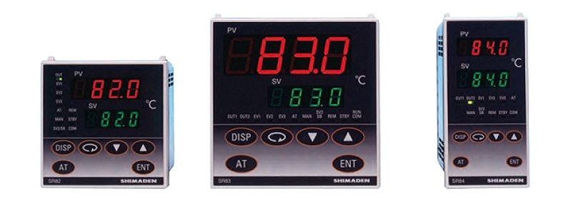
PID Controller SR80 Series ( SR82 / SR83 / SR84)
Shimaden SR80 series are suitable for applications with higher accuracy control is required.
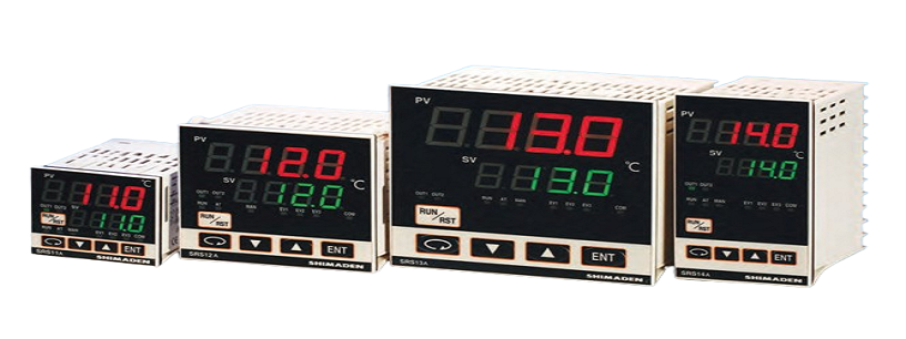
PID Controller SRS10A Series (SRS11A / SRS12A / SRS13A / SRS14A)
A controller with a space-saving depth of 62 x 65 mm compared to existing products with a depth of 100 mm. 3-point SV setting; 3 types of PID value can be set. Control output of ON/OFF hysteresis mode is selectable. Heating/cooling 2-output control (optional) can be selected. 4-pattern, 8-step program (optional) can be selected. 3-point maximum event output (optional) can be selected. Analog output (optional) can be selected. 2-point CT input (optional) can be selected. 4-point external control input maximum (optional), can be selected. Communication function (optional), master and slave mode can be used.
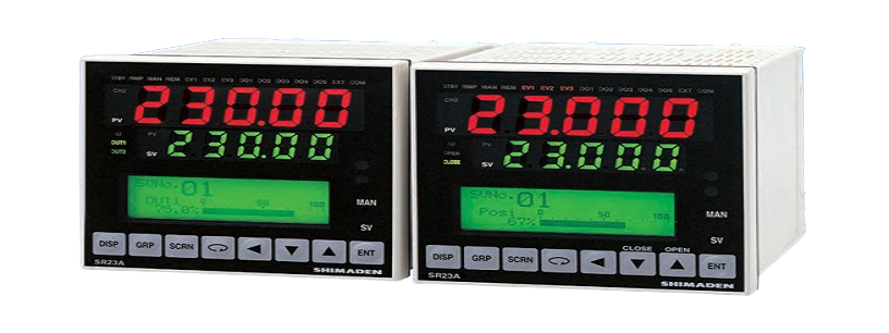
PID Controller SR23A
Feature:
- 2-channel controller (Basic type: 1-channel controller)
- Independent 2-loop / Internal Cascade / 2-input operation control
- High accuracy ± (0.1% FS + 1 digit)
- High Sampling Cycle 0.1 sec.
- High resolution 1/ 1000 °C display achieved
- *Only for R.T.D. input (scale: 0.000–30.000 °C)
- Auto-Tuning PID / Expert PID / Self-Tuning PID Multi-Setting of 10 Set Values
- Independent Multi -Input
- User Friendly Operation (Menu Driven: 4 Lines LCD Display)
- Easy Setting & Maintenance via Infrared COM port on the front panel
- Interface RS-232C/RS-485 (MODBUS / Shimaden)
- The front dust/splash-proof IP66
- Universal Power Supply (100–240V AC ±10%)
- Sensor power supply