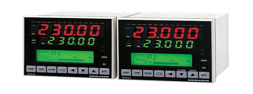
PID Controller SR23A
Feature:
- 2-channel controller (Basic type: 1-channel controller)
- Independent 2-loop / Internal Cascade / 2-input operation control
- High accuracy ± (0.1% FS + 1 digit)
- High Sampling Cycle 0.1 sec.
- High resolution 1/ 1000 °C display achieved
- *Only for R.T.D. input (scale: 0.000–30.000 °C)
- Auto-Tuning PID / Expert PID / Self-Tuning PID Multi-Setting of 10 Set Values
- Independent Multi -Input
- User Friendly Operation (Menu Driven: 4 Lines LCD Display)
- Easy Setting & Maintenance via Infrared COM port on the front panel
- Interface RS-232C/RS-485 (MODBUS / Shimaden)
- The front dust/splash-proof IP66
- Universal Power Supply (100–240V AC ±10%)
- Sensor power supply
1- Input Specification
- 1-output control
- 2-output control (Heat & Cool/Heat & Heat/Cool & Cool)
Ordering Information
|
ITEM |
CODE |
SPECIFICATIONS |
|||||||||||
|
SERIES |
SR23A‐ |
96 x 96 DIN size, high-performance digital controller EV 1 to 3 (3 points), DI 1 to 4 (4 points), DO 1 to 5 (5points) |
|||||||||||
|
BASIC FUNCTIONS |
SS |
Multi input, 1-input/1-output control |
|||||||||||
|
SD |
Multi input, 1-input/2-output control |
||||||||||||
|
CONTROL OUTPUT 1 |
Y |
Contact 1c, contact rating: 240V AC 2.5A/resistive load, 1A/inductive load |
|||||||||||
|
I |
Current 4–20mA DC, Load resistance: max. 600Ω |
||||||||||||
|
P |
SSR drive voltage output 12V±1.5V DC, Load current: max. 30mA |
||||||||||||
|
V |
Voltage 0–10V DC, Load current: max. 2mA |
||||||||||||
|
CONTROL OUTPUT 2 (Select N- for basic |
N‐ |
None |
|||||||||||
|
Y‐ |
Contact 1c, contact rating: 240V AC 2.5A/resistive load, 1A/inductive load |
||||||||||||
|
I‐ |
Current 4–20mA DC, Load resistance: max. 600Ω |
||||||||||||
|
P‐ |
SSR drive voltage output 12V±1.5V DC, Load current: max. 30mA |
||||||||||||
|
V‐ |
Voltage 0–10V DC, Load current: max. 2mA |
||||||||||||
|
REMOTE SETTING INPUT/HEATER BREAK ALARM (FOR SINGLE- PHASE) *1 |
04 |
REMOTE SETTING INPUT 4–20mA DC Input resistance: 250Ω |
Non-insulated input |
||||||||||
|
05 |
REMOTE SETTING INPUT 1–5V DC |
||||||||||||
|
06 |
REMOTE SETTING INPUT 0–10V DC |
||||||||||||
|
14 |
REMOTE SETTING INPUT 4–20mA DC |
Insulated input |
|||||||||||
|
15 |
REMOTE SETTING INPUT 1–5V DC Input resistance: approx. 600kΩ |
||||||||||||
|
16 |
REMOTE SETTING INPUT 0–10V DC Input resistance: approx. 570kΩ |
||||||||||||
|
31 |
Heater break alarm* (heater current 30A with CT) |
Selectable only when Control Output 1 or 2 is |
|||||||||||
|
32 |
Heater break alarm* (heater current 50A with CT) |
||||||||||||
|
ANALOG OUTPUT 1 |
0 |
None |
|||||||||||
|
3 |
0–10mV DC, Output resistance: 10Ω |
||||||||||||
|
4 |
4–20mA DC, Load resistance: max. 300Ω |
||||||||||||
|
6 |
0–10V DC, Load current: max. 2mA |
||||||||||||
|
ANALOG OUTPUT 2 or SENSOR POWER SUPPLY |
0 |
None |
|||||||||||
|
3 |
ANALOG OUTPUT 2 0–10mV DC, Output resistance: 10Ω |
||||||||||||
|
4 |
ANALOG OUTPUT 2 4–20mA DC, Load resistance: max. 300Ω |
||||||||||||
|
6 |
ANALOG OUTPUT 2 0–10V DC, Load current: max. 2mA |
||||||||||||
|
8 |
Sensor power supply 24V DC 25mA |
||||||||||||
|
Additional external output control signal (DI/DO) *2 |
0 |
None |
|||||||||||
|
1 |
DI 5 to 10 (6 points), DO 6 to 9 (4 points) |
||||||||||||
|
2 |
DI 5 to 10 (6 points), DO 6 to 13 (8 points) |
||||||||||||
|
COMMUNICATION FUNCTION |
0 |
None |
|||||||||||
|
5 |
RS‐485 |
Shimaden standard protocol / MODBUS (RTU/ASCII) communication protocol |
|||||||||||
|
7 |
RS‐232C |
||||||||||||
|
REMARKS |
0 |
Without |
|||||||||||
|
9 |
With |
||||||||||||
*1 When switching the SV No. by DI, 10 points of DI (CODE 1 or 2) are required.
*2 Ten DI points (code 1 or 2) are required for switching the SV No. by DI.
Optional Accessories
|
Name |
Model |
Description |
|
Shunt Resistor |
QCS002 |
250Ω, external input resistance at current input |
|
Relay Unit |
AP2MC |
Converts open collector output to contact output. 2 circuits built-in |
2- Input Specification
- 2-input/2-output control (independent 2-loop control)
- Internal cascade control *Output for control is output to Control Output 2.
- 2-input operation/1-output control (1-loop control by max. value, min. value, average value, deviation value operation)
- 2-input operation/2-output control (1-loop heat & cool/heat & heat/cool & cool control by max. value, min. value, average value, deviation value operation)
Ordering Information
|
ITEM |
CORD |
SPECIFICATIONS |
|||||||||||
|
SERIES |
SR23A‐ |
96 x 96 DIN size, high-performance digital controller EV 1 to 3 (3 points), DI 1 to 4 (4 points), DO 1 to 5 (5points) |
|||||||||||
|
BASIC FUNCTIONS *2, *3 |
DL |
Multi input, independent 2-loop control |
|||||||||||
|
DC |
Multi input, internal cascade control |
||||||||||||
|
DS |
Multi input, 2-input operation/1-output control |
||||||||||||
|
DD |
Multi input, 2-input operation/2-output control |
||||||||||||
|
CONTROL OUTPUT 1 *1 |
Y |
Contact 1c, contact rating: 240V AC 2.5A/resistive load, 1A/inductive load |
|||||||||||
|
I |
Current 4–20mA DC, Load resistance: max. 600Ω |
||||||||||||
|
P |
SSR drive voltage output 12V±1.5V DC, Load current: max. 30mA |
||||||||||||
|
V |
Voltage 0–10V DC, Load current: max. 2mA |
||||||||||||
|
CONTROL OUTPUT 2 |
Y‐ |
Contact 1c, contact rating: 240V AC 2.5A/resistive load, 1A/inductive load |
|||||||||||
|
I‐ |
Current 4–20mA DC, Load resistance: max. 600Ω |
||||||||||||
|
P‐ |
SSR drive voltage output 12V±1.5V DC, Load current: max. 30mA |
||||||||||||
|
V‐ |
Voltage 0–10V DC, Load current: max. 2mA |
||||||||||||
|
REMOTE SETTING INPUT/ HEATER BREAK ALARM (FOR SINGLE-PHASE) *4 |
04 |
REMOTE SETTING INPUT 4–20mA DC Input resistance: 250Ω |
Non-insulated input |
||||||||||
|
05 |
REMOTE SETTING INPUT 1–5V DC Input resistance: approx. 600kΩ |
||||||||||||
|
06 |
REMOTE SETTING INPUT 0–10V DC Input resistance: approx. 570kΩ |
||||||||||||
|
14 |
REMOTE SETTING INPUT 4–20mA DC Input resistance: 250Ω |
Insulated input |
|||||||||||
|
15 |
REMOTE SETTING INPUT 1–5V DC Input resistance:approx. 600kΩ |
||||||||||||
|
16 |
REMOTE SETTING INPUT 0–10V DC Input resistance:approx. 570kΩ |
||||||||||||
|
31 |
Heater break alarm (heater current 30A with CT) |
Selectable only when Control Output 1 or 2 is Y or P |
|||||||||||
|
32 |
Heater break alarm (heater current 50A with CT) |
||||||||||||
|
ANALOG OUTPUT 1 |
0 |
None |
|||||||||||
|
3 |
0–10mV DC, Output resistance: 10Ω |
||||||||||||
|
4 |
4–20mA DC, Load resistance: max. 300Ω |
||||||||||||
|
6 |
0–10V DC, Load current: max. 2mA |
||||||||||||
|
ANALOG OUTPUT 2/ SENSOR POWER SUPPLY |
0 |
None |
|||||||||||
|
3 |
ANALOG OUTPUT 2 0–10mV DC, Output resistance: 10Ω |
||||||||||||
|
4 |
ANALOG OUTPUT 2 4–20mA DC, Load resistance: max. 300Ω |
||||||||||||
|
6 |
ANALOG OUTPUT 2 0–10V DC, Load current: max. 2mA |
||||||||||||
|
8 |
Sensor power supply 24V DC 25mA |
||||||||||||
|
Additional external output control signal (DI/DO) *5 |
0 |
None |
|||||||||||
|
1 |
DI 5 to 10 (6 points), DO 6 to 9 (4 points) |
||||||||||||
|
COMMUNICATION FUNCTION |
0 |
None |
|||||||||||
|
5 |
RS‐485 |
Shimaden standard protocol/ MODBUS (RTU/ASCII) communication protocol |
|||||||||||
|
7 |
RS‐232C |
||||||||||||
|
REMARKS |
0 |
Without |
|||||||||||
|
9 |
With |
||||||||||||
*1 Independent 2-loop control, internal cascade control, 2-input operation/1-output control and 2-input operation/2-output control are all supported in the 2-input specification. This controller is shipped with the function selected at BASIC FUNCTION set.
*2 In an internal cascade control specification, slave output for control is output to Control Output 2. Select the same specification as Control Output 2 for Control Output 1.
*3 In a 2-input operation/1-output control specification, the output for control is output to Control Output 1. Select the same specification as Control Output 1 for Control Output 2.
*4 In a 2-output specification, the heater break alarm is used by either of Control Output 1 or 2.
Optional Accessories
|
Name |
Model |
Description |
|
Shunt Resistor |
QCS002 |
250Ω, external input resistance at current input |
|
Relay Unit |
AP2MC |
Converts open collector output to contact output. 2 circuits built-in |
Releted Products
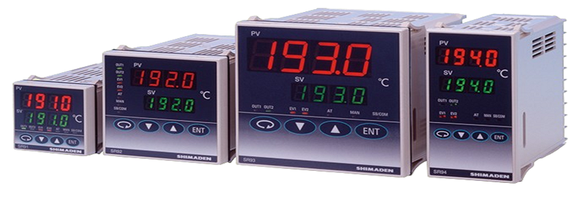
PID Controller SR90 Series ( SR91/ SR92 / SR93 / SR94)
Feature:
- Multi-input and multi-range performance
- Large 20mm bright display (SR93)
- Readable from a distance and in a low light area
- 2-output heating and cooling control available
- RS232C or RS485 Interface (MODBUS / Shimaden) available
- Dust and splash proof front panel equivalent to IP66
- A wide selection of additional functions (optional) is available to suit various needs.
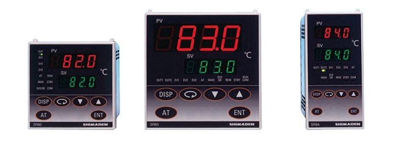
PID Controller SR80 Series ( SR82 / SR83 / SR84)
Shimaden SR80 series are suitable for applications with higher accuracy control is required.
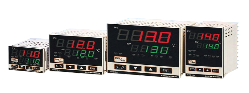
PID Controller SRS10A Series (SRS11A / SRS12A / SRS13A / SRS14A)
A controller with a space-saving depth of 62 x 65 mm compared to existing products with a depth of 100 mm. 3-point SV setting; 3 types of PID value can be set. Control output of ON/OFF hysteresis mode is selectable. Heating/cooling 2-output control (optional) can be selected. 4-pattern, 8-step program (optional) can be selected. 3-point maximum event output (optional) can be selected. Analog output (optional) can be selected. 2-point CT input (optional) can be selected. 4-point external control input maximum (optional), can be selected. Communication function (optional), master and slave mode can be used.